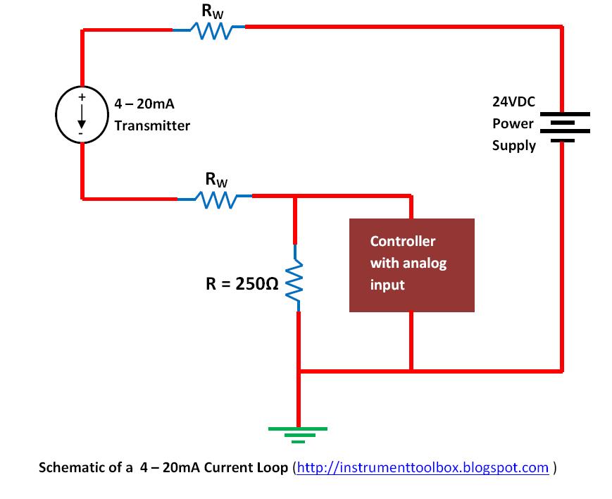
Test equipment parts & accessories business & industrial 0-1000 ohm to How a 4-20 ma transmitter works? 4-20ma circuit schematic
Fundamentals, System Design, and Setup for the 4 to 20 mA Current Loop
4 to 20 ma current loop output signal Wire two transmitter loop powered transmitters wiring ma 20 power cable types advantages only signalling 4-20ma circuit schematic
How to wire a 4-20ma transmitter?|4wire & 2wire (loop powered
20ma loop current ma 20 signal system setup wire fundamentals isolated sensor power supply ni io share transducer control dataSchematic ads1115 breakout 20ma using sensors pt100 board 12v adcs sch How to do the 4-20ma wiring?Fundamentals, system design, and setup for the 4 to 20 ma current loop.
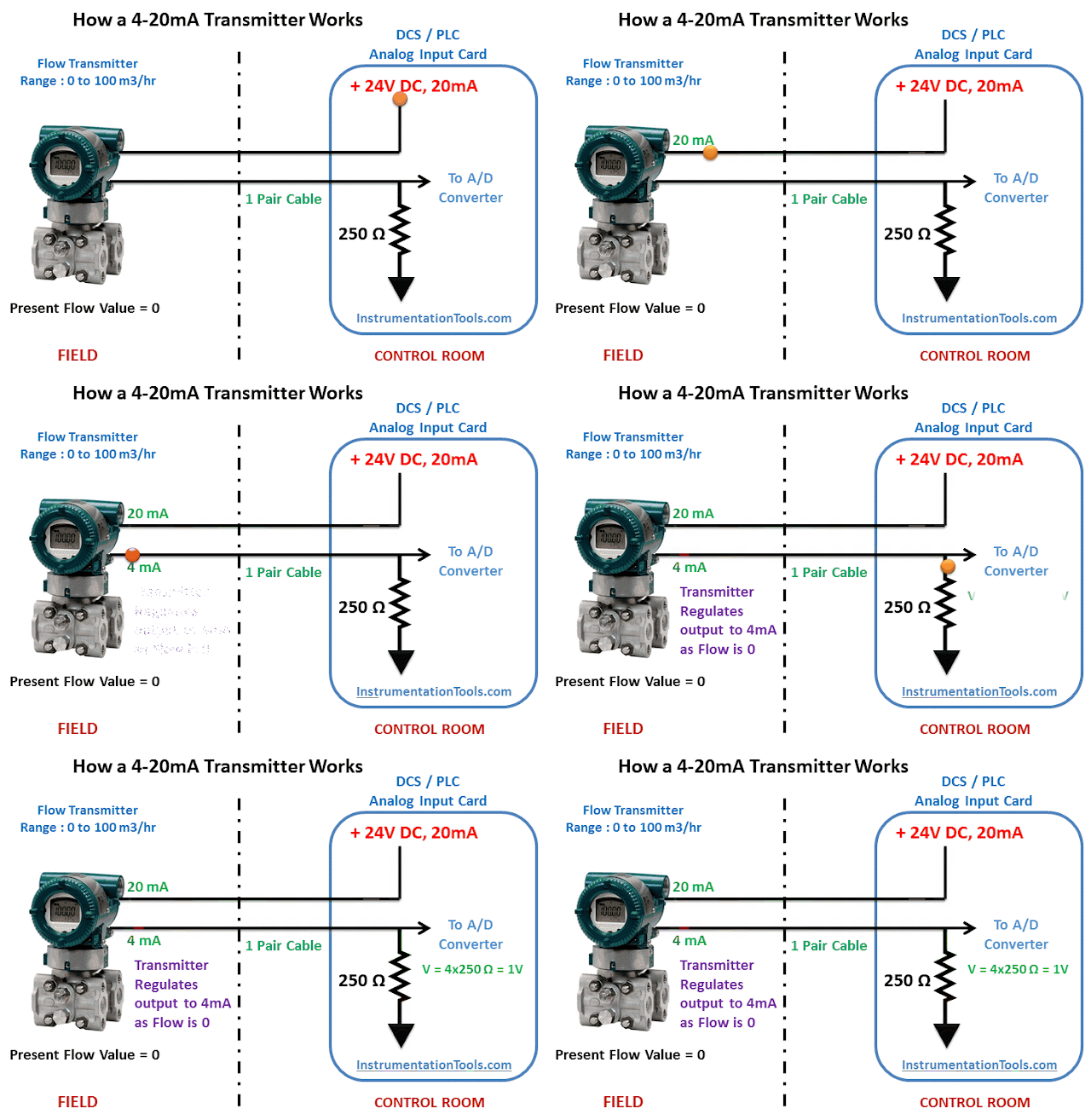
20ma wire output signal transmitter4-20ma to 0-10v converter schematic 20ma transmitter works ma loop current process 20 circuit schematic gif instrumentation converter working animation principle dc tools instrumentationtools signals20ma signal converter rs232 voltage 5vdc resistance vdc volt supply resistor ohm volts sensorsone required allow.

Reading a 4-20ma schematic diagram
0-5v to 4-20ma signal conversion module v/i converter voltage toCurrent loop to voltage converter (4-20ma to 0-3.3v/ 0-5v/ 0-10v The science of 4 to 20 ma current loops4-20 ma transmitter wiring: 4wire transmitter connection & 2wire loop.
4 20ma circuit schematic4 20ma transmitter circuit schematic Electronic – are transmitters always required for industrial sensors[diagram] circuit diagram 4 20ma.

Wit wire transducer wiring diagram ma transmitter wiring types
4-20 ma transmitter wiring types : 2-wire, 3-wire, 4-wireReading a 4-20ma schematic diagram Loops bapihvac20ma converter module 5v.
4 20ma signal generator circuit diagram4-20ma loop powered wiring diagram 4 20ma pressure transducer wiring diagram database2 wire 4-20ma wiring diagram.

4 to 20 ma current loop output signal
.
.


4 20ma Transmitter Circuit Schematic
4-20 mA Transmitter Wiring Types : 2-Wire, 3-Wire, 4-Wire

adc - 4-20ma current loop and ESP32 - Electrical Engineering Stack Exchange

ground - 4-20mA with 12V sensors using ADS1115 ADCs - Electrical

0-5V to 4-20mA Signal Conversion Module V/I Converter Voltage to

How to do the 4-20mA Wiring? | Instrumentation and Control Engineering

The Science of 4 to 20 mA Current Loops - Application Note - BAPI

How a 4-20 mA Transmitter Works? - Instrumentation Tools